
1 全体アーキテクチャ
1.1 5G アーキテクチャ概要
The 5G architecture is defined as service-based and the interaction between network functions is represented in two ways. [TS 23.501 4.1]
- A service-based representation, where network functions (e.g. AMF) within the Control Plane enables other authorized network functions to access their services. This representation also includes point-to-point reference points where necessary.
- A reference point representation, shows the interaction exist between the NF services in the network functions described by point-to-point reference point (e.g. N11) between any two network functions (e.g. AMF and SMF).
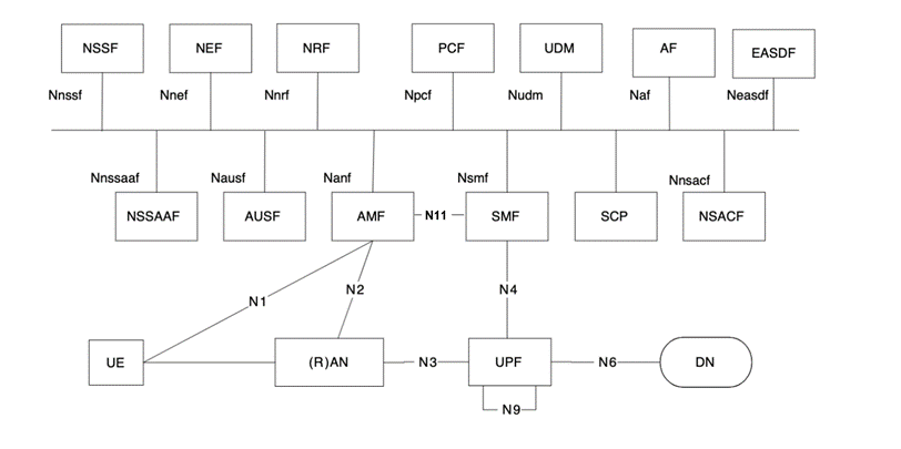
図 3‑1 Non-Roaming 5G System Architecture [TS 23.501 fig 4.2.3-1]
1.2 Trusted non-3GPP概要
From 3GPP point of view, TNGF is a trusted gateway NF, which provides connectivity to UE through a trusted access network, i.e., UE is connected to a trusted access point (TNAP) using non-3GPP wireless or wired access technology. In this context, TNAN is composed of TNAP and TNGF, as illustrated in 図 3‑2 . This figure shows the non-roaming architecture for 5GCN with trusted non-3GPP access, presenting the components of TNAN and the relationship between UE, trusted network, and 5GCN. Similar to untrusted networks, UE using 3GPP access via gNodeB can also connect to trusted non-3GPP access via TNGF.
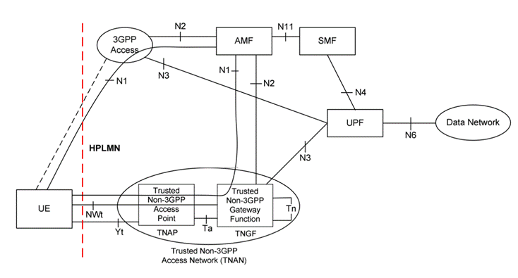
図 3‑2 Non-roaming architecture for 5G Core Network with trusted non-3GPP access [TS 23.501 fig 4.2.8.2.1-2]
When the UE decides to use trusted non-3GPP access to connect to a 5G Core Network in a PLMN:
– the UE first selects a PLMN([TS 24.502, 5.1]); and then
– the UE selects a non-3GPP access network (a TNAN) that supports trusted connectivity to the selected PLMN. In this case, the non-3GPP access network selection is affected by the PLMN selection.
A UE that accesses the 5G Core Network over a non-3GPP access shall, after UE registration, support NAS signaling with 5G Core Network control-plane functions using the N1 reference point. When a UE is connected via a NG-RAN and via a non-3GPP access, multiple N1 instances shall exist for the UE i.e. there shall be one N1 instance over NG-RAN and one N1 instance over non-3GPP access. [TS 23.501, 4.2.8.1]
1.3 TNGFアーキテクチャ視点纏め
1.3.1 全体視点
1.3.1.1 技術領域
TNANは、従来のgNBと比べて、WLAN領域と3GPP領域のインターワークする必要がある
- 【3GPPドメイン】gNB機能と一致する5GCN接続のRAN機能
3GPP規定するgNB経由5GSと同じ動作(UE Registration, PDU Session Establishment/Modification)
規格資料は3GPP TS(Technical Specification)形式で公開 (HP: https://portal.3gpp.org/)
- 【WLANドメイン】802.1Xを実現するWiFi接続機能
IEEEとIETF規定する802.1X(EAP,RADIUS), IPsecの動作
規格資料は RFC(Request for Comments)(HP: https://www.rfc-editor.org/)
TNANはインターワークなので、以下の二つ視点の既存技術比較することがある
- Non-3GPP Accessと 3GPP Accessの比較
Non-3GPPは一般なgNB接続の以外に、WiFi接続を提供
既存CNの改修を抑えるため、N3IWFとTNGFがGatewayとして、従来なN1N2をほぼ流用する
従来なKSEAFとKAMFを活用して、WLANのセキュリティー接続をサポート[TS 23.502 4.12a.2.2 ]
ハイブリッドネットワークになると、QoS制御するため、まだギャップが多い[TS 24.502 4.4]
- Untrusted(N3IWF)と Trusted(TNGF)の比較
N3IWFの場合、WLAN接続と5GCN接続は、別々で行う、互いに依存性は少ない
TNGFの場合、WLAN接続と5GCN接続は一つプロセスに混在、しっかり連携する
一旦IPsecを繋がって、IPsec上のCP signalとUP data traffic違いところがすくない[TS 23.502 4.12a.7]
QoS profile関連いくつ設定は、N3IWFはオプションだが、TNGFは必須
1.3.1.2 プロセスマッピング
WLANと3GPPのInterworkingがあるので、TNANの場合、以下の既存の三つ専門プロセスを一つにマージした。
- 802.1X(EAP)の認証(RFC3748&RFC3579)
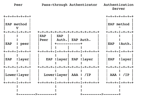
図 3‑3 Pass-through Authenticator access [RFC3748]
図 3‑4 conversations between an peer, NAS, and RADIUS server [RFC3579]
- IPsec(IKEv2)接続(RFC7296)

図 3‑5 Endpoint to Endpoint Tunnel [RFC7296 Figure 3]
図 3‑6 IKEv2 initial exchanges [IBM DOC]
- 5G認証接続(3GPPに定義)
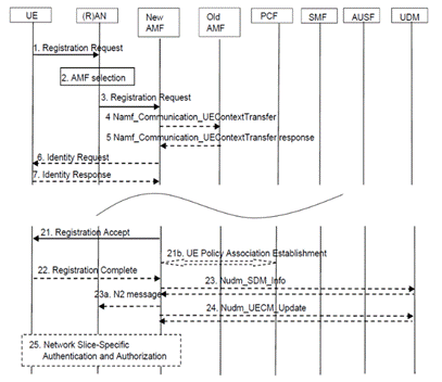
図 3‑7 part of Registration procedure [TS23.502 Figure 4.2.2.2.2-1]
- 三つプロセスのマッピング
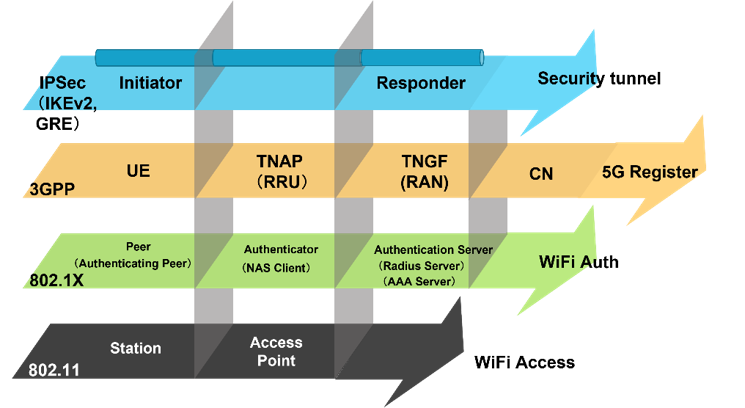
図 3‑8 プロセス別のロールマッピング
1.3.2 ネットワーク視点
TNGFはN3IWFと違いで、802.1x認証(AAA認証)と5G UE認証が混在しているので、認証する際に、YtとTaを特別に実装する必要。
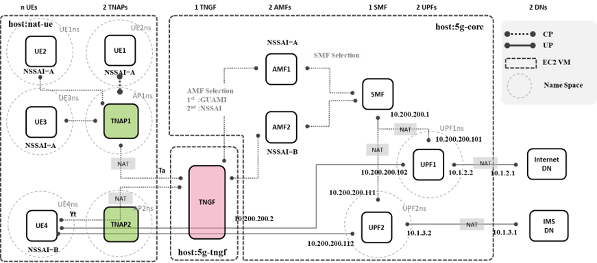
図 3‑9 ネットワーク構成図
Ta shall be able to
Carry EAP-5G traffic and user location information before the NWt connection is established between the UE and the TNGF.
Allow the UE and the TNGF to exchange IP traffic.
In deployments where the TNAP does not allocate the local IP addresses to UE(s), Ta shall be able to:
Allow the UE to request and receive IP configuration from the TNAN (including a local IP address), e.g. with DHCP. This is to allow the UE to use an IP stack to establish a NWt connection between the UE and the TNGF.
NOTE: The “local IP address” is the IP address that allows the UE to contact the TNGF; the entity providing this local IP address is part of TNAN and out of 3GPP scope In this Release of the specification, Ta is not specified. [TS23.501,4.2.8.3.2]
1.3.3 プロトコルスタック視点
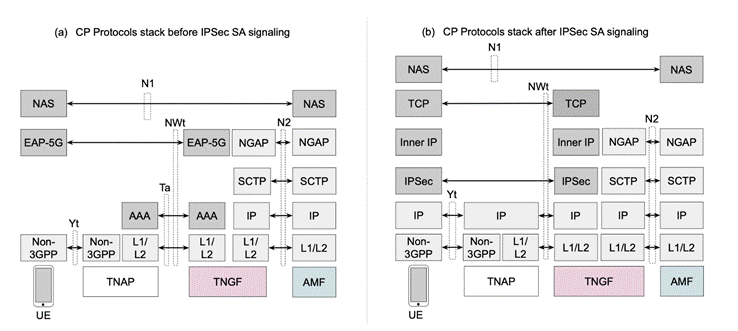
図 3‑10 NWtのCPプロトコルスタック
以上の図により、認証する前に、CP通信はNAS Over EAP-5G Over RADISU(Ta)/EAPol(Yt)で行う。一旦UEがIPがLocateすると、通常IPsec立ち上げると同じで、IKEv2 SA(IKE_SA_INIT)とIPsec SA(IKE_SA_AUTH)を行う。一旦IPsec上のTCP(NWt)接続を行って、次のCPとUP(GRE over IPsec)処理は、全部はNWtで行う。
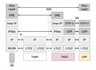
図 3‑11 NWtのUPプロトコルスタック
1.3.4 Procedure観点
今回PoCは、UEと5G CNの間の二つプロシージャ(UE 登録&認証、PUD セッション構成)を中心として、関連ユースケースを検証する。他の観点も、3GPP定義するProcedureを回って、実現方法を考える。
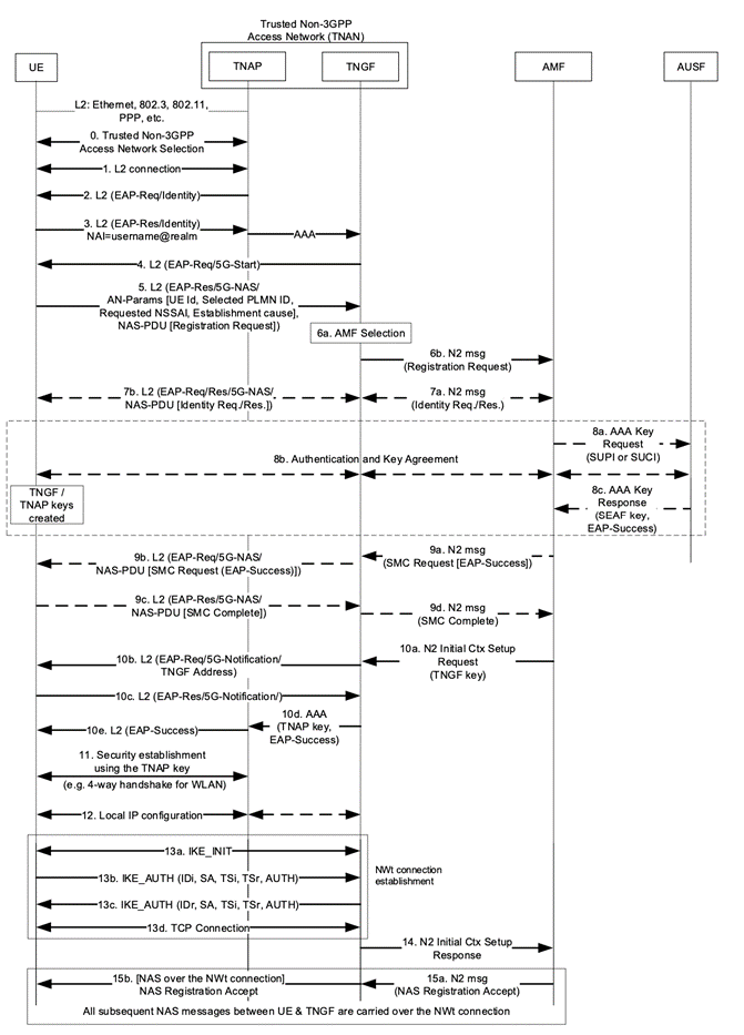
図 3‑12 Registration via trusted non-3GPP access([TS23.502 4.12a.2.2 ])
1.3.5 NFsマイクロサービス間通信観点
今はAWSクラウドで関連サービスを優先順位でVMのシングルサービスからKubernetesのコンティナサービスを構築している。
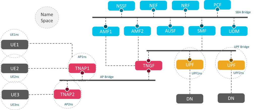
図 3‑13 サービス構築方式
1.4 UE認証処理
表 5‑4 プロトコルメッセージ制御
| プロトコル | 利用目的 | 処理モジュール | 参考標準 |
| 汎用EAP(EAP-Req/EAP-Success) | EAP認証 | RADIUSサービス | RFC 3579 |
| 専用EAP(EAP5Gの5G-start,5G-NAS) | UE 5G認証 | RADIUSサービス | TS 24.502 9.3.2 |
| 認証EAP AKA` or 5G AKA | UE 5G認証 | RADIUS サービス | TS 33.501 6.1.3 RFC 9048 |
| RADIUSメッセージ | AAA認証 | RADIUSサービス | RFC 3748 |
| IKEv2 | IPsec立ち上げる | IKEサービス | RFC 7296 |
| NASメッセージ | N2通信 | NGAPクライアント | TS 24.501 4.7 |
| GREメッセージ | UPのYt通信 | IKEサービス | RFC 2784 |
| GTP-U | N3 | GTPサービス | TS 29.281 |
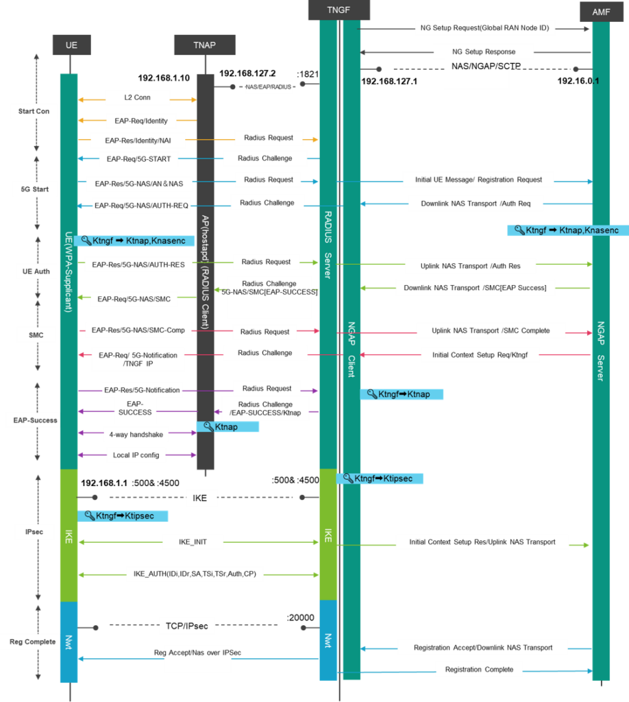
図 5‑3 TNGF経由でUE認証
RADIUS認証とIKE認証の二つプロセスは別々に非同期で行うので、同じUEを特定するため、二つプロセス中のUE Indentityを設定する必要がある。RADIUSの場合は、GUTIまたはSUCIの生形式、IKEの場合は、GUTIまたはSUCIのNAI形式で。生のUEIDにより、図 5‑4の通り、同じUEが特定する。
RADIUS場合、AN ParamsでTNGFにUE ID送信する以外に、NAS PDU経由で、AMFにUE IDも送信する。AMF側は、従来のgNB処理と同じで、関連認証とUE Contextを到底する。
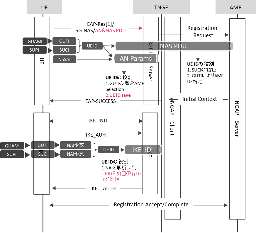
図 5‑4 N1、RADIUSとIKE段階のUE Identity